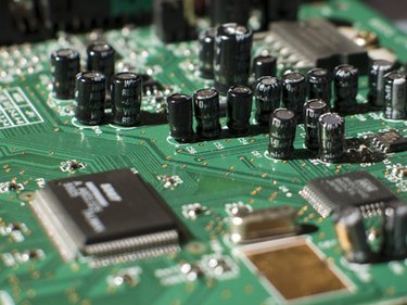
The circuit board is an integral component in electrical devices such as stereos, computers and guitar amplifiers. It's responsible for processing electrical signals and turning them into information. The nature of that information depends on the type of circuit. For example, the circuit board in a guitar amplifier will transform an electrical signal into an audio signal. Faults on the circuit board can cause the electrical device to malfunction or stop working. You can test the points on a board to identify the location of a fault.
Step 1
Visually inspect the board. By examining the board and the surface-mounted components, you can identify obviously damaged or disconnected parts before beginning a points test. Look for blown fuses and transistors; both would have brown coloration. Look out for obvious signs of oxidation and corrosion such as rust. Inspect the wires to make sure all of the components are connected.
Video of the Day
Step 2
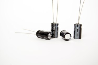
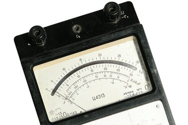
Test the capacitors. A capacitor blocks direct current and allows alternating current to pass. Turn on the power. Discharge the capacitor by touching its leads together. Set the meter to the highest resistance setting. Turn off the power. Probe the capacitor and turn the power back on. If the meter reading is zero, the capacitor is shorted.
Step 3
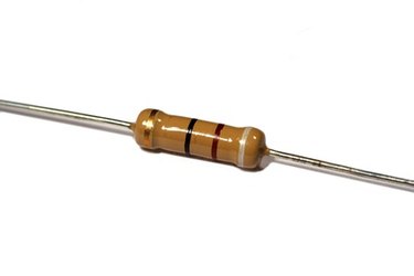
Test the resistance points. Resistors manage the flow of current through the circuit board. They attenuate the voltage so that it is proportionate to the current. Disconnect the power supply from the circuit board. Follow the signal path on the board so that you can locate the first resistor in the chain. Place your meter probe on the circuit directly after the first resistor. Set your volt meter to the "resistance" setting. Power the board and make a note of the reading. The meter will signal a zero reading if the resistor has shorted or is not connected. A malfunctioning resistor will prevent any signal from passing through. Consult the user's manual to determine the expected voltage. If the meter gives a reading identical or approximate to the expected voltage for the device, move on to the next resistor in the chain.
Step 4
Replace faulty resistors. Use a highlighter pen or masking tape to mark faulty resistors. Unscrew the circuit board and flip it over. Melt the connection with a soldering iron and remove the resistor from the board. Mount a new resistor on the board and solder it from underneath.
Step 5
Retest the resistance points. Repeat the resistor test on the new resistors to ensure they function correctly.
Video of the Day