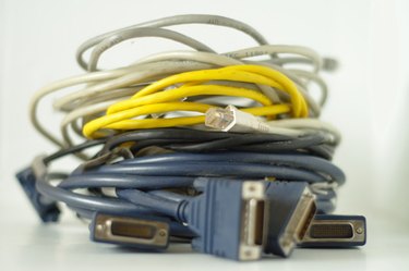
Serial RS232 cables rely on a specification that has been modified considerably over the years into a variety of pinouts, connectors and data cable configurations. One of the more common RS232 serial cable standards requires two 25-pin D-Sub connectors configured with crossover transmit and receive lines. This cable is used by devices that require asynchronous or hardware handshake serial communications. Construct your own DB25-to-DB25 RS232 serial cable with a few parts and basic soldering skills.
Step 1
Create four jumper wires from a two-inch piece of data cable. Remove the protective outer sheathing with a wire stripper. Strip a quarter-inch of insulation from four of the exposed wires and set them aside.
Video of the Day
Step 2
Strip off two inches of the protective sheath from both ends of the six-foot data cable. Strip a quarter-inch of insulation from both ends of the exposed red, black, yellow, green and blue wires. Twist the copper strands at the end of each wire tightly so that no loose strands are visible. Cut off the remaining unused wires at both ends of the cable.
Step 3
Plug in the soldering iron and allow it to heat up for five minutes. Then, solder the wires from the six foot data cable to the male DB25 connector according to the following color scheme:
Pin 2 - Red wire Pin 3 - Yellow wire Pin 7 - Black wire Pin 20 - Green wire Connector shell - Blue wire
Note that pin numbers are identified on the back of the connector in small writing by each pin.
Step 4
Attach and solder one of the two-inch jumper wires prepared earlier to pins 4 and 5 on the back of the DB25 male connector. Then attach and solder a two-inch jumper wire to pins 6 and 8 on the back of the DB25 male connector.
Step 5
Attach and solder one of the two-inch jumper wires prepared earlier to pins 4 and 5 on the back of the DB25 female connector. Attach and solder a two-inch jumper wire to pins 6 and 8 on the back of the DB25 female connector.
Step 6
Solder wires from the other end of the six foot data cable to the back of the female DB25 connector using the following pinout:
DB25 male pin 3 (yellow wire) to DB25 female pin 2 DB25 male pin 2 (red wire) to DB25 female pin 3 DB25 male pin 20 (green wire) to DB25 female pin 5 DB25 male pin 7 (black wire) to DB25 female pin 7 DB25 male shell (blue wire) to DB25 female shell
Step 7
Position the connector covers on the DB25 connectors. Snap the covers in place and tighten the screws.
Video of the Day